Final project
CATHOUSE PROJECT

Content of page
A list of materials required for the project fabrication.
A list of materials required for the project fabrication.
Seeed XIAO esp32s3
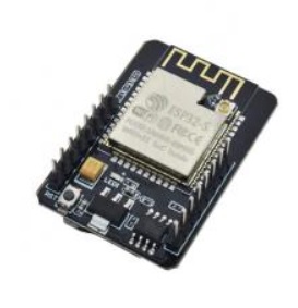
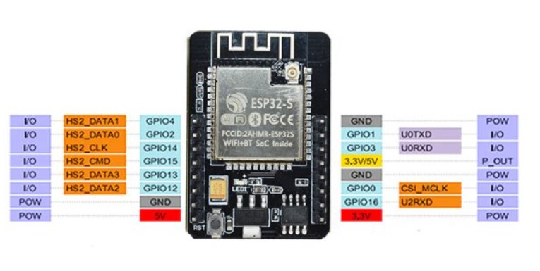 The combination of a Wi-Fi module with a high-performance microcontroller ESP32, OV2640 video camera, micro-SD memory card slot, and additional 4MB of RAM allows for the creation of portable devices for security systems, video surveillance, and smart home systems.
Specifications:
Controller: ESP32, 2 cores, 32-bit
Processor clock frequency: 240 MHz / 600 DMIPS
RAM: Built-in: 520 KB / External: 4 MB
Supported interfaces: UART/SPI/I2C/PWM/ADC/DAC
Built-in Lwip and FreeRTOS
Supports STA/AP/STA + AP operating modes
Supports Smart Config/AirKiss network distribution
Power supply voltage: 5V
Camera module: OV2640 (included)
Resolution: 2 MP
Supported cameras: OV2640 and OV7670
Data storage: micro-SD
Size: 27 x 39 mm
Weight: 10 g
Servo motor sg 90
Servo drives are a family of devices consisting of a motor and a negative feedback control system. The main distinguishing feature of such drives is the ability to precisely control motion parameters, for example, speed, force or shaft position. In the hobby, servos usually control the last parameter - the position of the shaft.
Laser diode module point 5mW 5V red 650nm
PLA Filament
bolts m2
carbon fiber
textolite fr1
solder
The final cost calculation of materials for the project is provided here.
PCB Designe
Then I started designing the pcb board. How It was I descrabe inFor designed PCB board for my Final project I used the next element
XIAO esp32s3
Servo SG90 - 2 items
Servo drives are a family of devices consisting of a motor and a negative feedback control system. The main distinguishing feature of such drives is the ability to precisely control motion parameters, for example, speed, force or shaft position. In the hobby, servos usually control the last parameter - the position of the shaft.
The logic of the servo drive is quite simple. A control PWM signal is supplied to the input, which is compared with the signal generated by the feedback system. And if the feedback signal pulse duration is shorter than the PWM signal pulse duration, then the motor rotates in one direction, and if it is longer, then in the opposite direction. If the signal pulses coincide, then the engine remains motionless.
The important point here is that the duration of the feedback pulses is regulated by a built-in potentiometer, the position of the shaft of which is set by the motor shaft through a gear drive: where the motor shaft goes, so does the potentiometer handle. Thus, any movement of the motor shaft will be followed by a change in the length of the feedback signal pulses. This coupling forms feedback. You can see it in the servomotor diagram above.
laser 5 mWt
led green (It's very impotent to use green colour for indication working condition, because people are used to this color signifying positive things. In aviation, all working condition are marked in green, and emergency states are marked in red)
resistor 1kOhm
Connector 3 pin - 2 item
1 MOSFET for 5V
1. Creat a new projecr on KiCad.
2. Design electric schem.
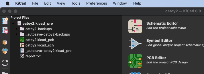
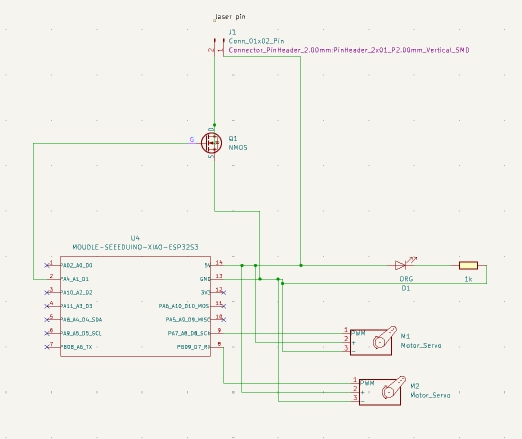
3. I creat new footprint for Laseer and for Servo. I used connectors for added them.

4. Performed the separation of the traces of the pcb board.
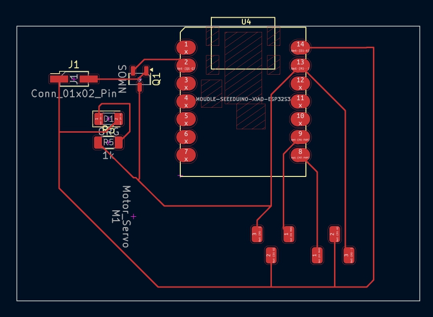
5. Export PCB Board to .svg file. (Choose Leyer F.Cu abd Eage.Cut)

6.Used Mods Ce fo export svg to .nc file. Open it with Universal g-code sender.


7. Board installation.
I used a 1 kOhm resistor because I plan to use a laser diode.
R= (V supply−V laser)/I laser
V supply= 5V
V laser=3.3 V
I laser=1.7м А
R= 1 kOhm
For the first time, I used the method of soldering with the help of paste and a hair dryer. It takes some getting used to, but overall the impressions are good.

you can find kickad files here
you can find svg files here
Hardwere part
A cat needs a cozy place to rest, so I decided to make a house.
.jpg)
.jpg)
How I made this house is described in detail in week seven at the link There are also original design files.
Software part of the project
laser pointer programming
To make a laser pointer for a cat, I will need the following components xiao esp32s3 sense, two sg90 servos and a laser diode. The servo and diode programming process is described in week 9. During the development process, the work was checked by the future owner of the device.
How I programmed the microcontroller to control the servo is described in detail in week 9 at the link There is also a file with the program code.
In order for the mother to watch her pet remotely, I need to program the esp32s3P
first of all, I used a simple sketch to connect to wi-fi.

The next step I added was creating a server. Since I used a modified sketch that used pins that are not on my esp, I had problems with the board constantly rebooting. After I fixed it. The server is up and running.
The next stage is servo control. I also changed the sketch to control two servos and a laser. The sketch was successful.
Then I created a separate sketch to output the video from the camera to the server. This sketch also worked

The last task is to combine the sketches
For this, I used the sketch in the link
Open Filebut at the moment I can only see videos on the server. I don't understand why the servo control is not displayed.


System integration
To put the pieces of my project together, I started with the laser pointer mount. I found it at this link.

As a result, I used only one of the three elements - a mount for two servos between themselves. I printed it on a 3D printer
The next task was to design the case. I also decided to make its main part with the help of 3D printing. Together with it, I also designed a stand for the servo.


the case also provided mounting for the board, holes for the camera and Type-C input and for wires.
I fixed the wires from the servo and the laser with the help of thermal insulators.
The back panel was designed and cut with a carbon fiber router. I found out later that it is dangerous for health. But it turned out to be a very good cover.
I described how I assembled the entire project into one device at the week of system integration here
Finally, the electronics are assembled in the case

The last step is fixing the device on the cat's house.

the final result of assembly and integration

Answers to questions
what tasks have been completed?
- manufacturing by milling a house for a cat
- programming of a microcontroller to transfer video to the server and control servomotors
- design and assembly of the case
what tasks remain?
clean the control interface from unnecessary functions
the microcontroller is connected to the network only from the laptop with which it was programmed, but it can be controlled from any device that is on the same network as it.
what has worked? what hasn't?
Everything worked, but with some caveats.
For the pointer, you need to use only servos that move in the range of 0 - 180 degrees. With a range of 360 degrees, the servo does not accept a command with a limit.
it was difficult to combine sketches for video transfer and servo control on one server.
what questions need to be resolved?
The problems were solved by dividing the control functions into different sketch files.
The main file describes the creation of a server with video transmission, and the camera_index.h file describes the control of servo motors.
what have you learned?
While working on the project, I learned literally all the skills that were used, but I had not done this before. Design of parameterized models, design of programs for milling, programming of microcontrollers and production of printed circuit boards
The first idea
The surveillance system for the area.
Camera with built-in motion sensor:
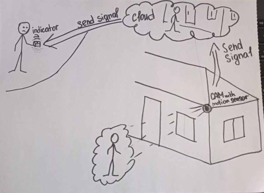
The camera can automatically activate when motion is detected within the private property.
The motion sensor helps in timely detection of potential intruders.
Notification to a remote indicator (LED remote control):
If the camera detects motion or potential intrusion, the system sends a notification to a remote indicator, such as an LED remote control.
The LED can flash or stay lit continuously, indicating the presence of an event.
Remote control:
The user can have a remote control to arm/disarm the system or check the security status.
Convenient control can be particularly useful for homeowners who are away from home.
Data storage system:
Provide a system for storing recordings or changes on a server or cloud storage.
Allow the homeowner to view archived recordings for event analysis. Mobile application:Develop a mobile application for devices so that homeowners can receive notifications and view video recordings in real-time.
Provide the ability to remotely control the system through the application.
Energy efficiency:
Pay attention to the energy efficiency of the system, especially if it operates continuously.
Provide the ability to adjust the activation time of the system to optimize energy consumption.